Conductor Materials: Layer-by-Layer Control from Metal to Structure
The life of a flexible conductor depends on how metal wires, fiber cores, insulation jackets and structural design work together. CHRYPOO offers options at every layer and can design products with or without insulation.
🧪
Metal Conductor Materials
Pure copper OFC (oxygen-free copper): extremely low oxygen content (≤0.001%) and high conductivity, ideal for high-end audio and speaker applications
Tin-copper alloy: a general-purpose alloy with the widest range of applications
MG high-strength copper: higher tensile strength, corrosion resistance and low resistance than tin copper, at a controllable cost
Silver-copper alloy: further improved conductivity, tensile strength, fatigue and heat resistance for high-performance uses
🧶
High-Strength Fiber Cores
Aramid fiber: meta / para aramid, high strength and heat resistance — the mainstream core in the wire & cable industry
PBO super fiber: even higher specific strength and modulus, for the most demanding uses
Carbon / glass fiber: light weight and high tensile strength with corrosion resistance
🛡️
Insulation & Jacket
PVC / PE / TPE: from general purpose to flexible dynamic cables — a balance of cost and performance
Silicone: withstands high and low temperatures, high dielectric strength, soft and long-lasting
Heat-shrink tubing: termination insulation and harness protection
🧵
Structural Design
Foil winding: metal foil wound around a fiber core — distributed stress, excellent flexibility
Stranded structure: multiple fine strands twisted together, balancing flexibility and current capacity
Braided structure: stable structure with high toughness and support, suited to high-power, high-dynamics and long-span scenarios
Parallel winding: low-loss structure with a small OD, used for high-frequency and tweeter-unit leads
⚡
Plating & Surface Treatment
Tin plating: prevents oxidation, improves solderability — friendly to harness and termination processing
Silver plating: benefits high-frequency transmission, for high-end speakers and precision signals
Nickel plating: heat and corrosion resistance for harsh environments
Surface treatment: anti-oxidation, anti-wear and anti-corrosion protection
✂️
Post-Processing: Cutting & Pre-Tin
Cut to length: cut to drawing length and tolerance, reducing waste at the customer end
Stripping: termination insulation stripped with controlled length and cut quality
Pre-Tin: pre-tinned ends improve soldering efficiency on the production line
Forming: pre-attached connectors, plugs, terminals, noise-damping cotton wrapping and more as needed
Insulation & Jacket Material Comparison
Data are typical industry ranges; actual performance is subject to the selected datasheet and measurements
Material
Temp. Range
Flexibility
Abrasion
Chemical
Typical Applications
PVC
-20 ~ 105 ℃
Good
Fair
Fair
General electronic wire, cost-sensitive designs
PE
-40 ~ 80 ℃
Fair
Fair
Good
High-frequency signal, low-loss transmission
TPE
-50 ~ 125 ℃
Excellent
Excellent
Good
Flexible dynamic cables, earphone & data cables
Silicone
-60 ~ 200 ℃
Excellent
Good
Fair
Extreme temperatures, medical & home appliances
Magnet-wire insulation (PEW / UEW / EIW)
130 ~ 180 ℃
Excellent
Fair
Fair
Dense winding, voice coils, transformers
Heat-shrink tubing
-55 ~ 125 ℃
Stiff after shrink
Excellent
Good
Termination insulation, harness protection
CHRYPOO Innovative Treatment Technology
CHRYPOO Innovative Treatment Technology
Speaker tinsel wire carries the signal and safeguards service life — the true "lifeline" of a loudspeaker. Building on nearly 20 years of tinsel-wire process expertise, CHRYPOO independently developed its innovative treatment technology to systematically solve four common industry problems.
The traditional cone-pierce threading process has largely been replaced by direct voice-coil attachment: tinsel wire is now one-third or more longer, with a much larger wire exit angle. Combined with rising digital-amplifier power, continuously falling loudspeaker F0 and increased stroke, the industry now places higher demands on the toughness, support, amplitude stability and solderability of tinsel wire.
Four Common Industry Problems
⚖️
Hardness vs. Toughness
The industry commonly adjusts by increasing rosin content: hardness goes up, but toughness goes down
During vibration the rosin-wax mixture tends to shed — the wire jumps randomly, strikes the damper or cone and creates unwanted noise
The root cause is insufficient support and toughness, not simply "making it harder"
HD slow motion of the "jump-rope" effect: slow motion clearly shows how the wire jumps during vibration.
🔥
Solder Wicking & Hardening Behind the Terminal
Lead-free solder has a higher melting point; terminal pads are large, iron temperatures high and heat recovery fast
Wire with excessively good solderability wicks behind the terminal (solder travels along the foil) and hardens — this failure accounts for up to 90% of tinsel-wire breakage
Silver-plated wire is especially prone due to strong tin-silver affinity; many customers were forced to switch to bare copper wire
Real footage of solder wicking, hardening and dusting (side-by-side): the clip compares solder wicking, hardening and dusting behind the terminal, left versus right.
❄️
Low-Temperature Embrittlement & Dusting
At low temperature the rosin-wax mixture loses viscosity and adhesion, so the wire embrittles and sheds powder
The powder contaminates voice coils, production equipment and magnet assemblies, causing noise
Viscosity also decays naturally after storage, causing dusting again — poor aging stability
🌾
Fuzz Affects Soldering
Aramid short fibers leave the copper foil about 75% covered, exposing fuzz on the rest
Aramid is heat-resistant, so fuzz can only be burned off with open flame — hard to control and unstable; over-burning also anneals the foil
Fuzz repels solder due to the "lotus effect", causing poor wetting and cold joints
20%–100%+
Tinsel Wire Life Improvement
Life improvement of CHRYPOO's innovative treatment versus conventional treatment under identical materials and test conditions.
≈90%
Share of Wicking-Hardening Breakage
Proportion of wicking-hardening failures among tinsel-wire breakage — a common industry pain point.
4℃ / -18℃
15–30 Days Low-Temp, No Embrittlement
Stored 15–30 days at 4℃ (refrigerated) or -18℃ (frozen): bending shows no embrittlement and no dusting.
Note: The life-improvement, low-temperature test and breakage-proportion data above come from the company's internal like-for-like comparison tests and public industry case statistics. Actual results vary with materials, structure, motion conditions and environment — please rely on testing under your own application conditions.
Eight Core Features of CHRYPOO Innovative Treatment Technology
1
Room-Temperature Hardness & Toughness Combined Excellent hardness and toughness at 20℃; repeated 180° bending of a 5 mm wire shows no embrittlement or dusting.
2
Stable Toughness at Low Temperature Maintains proper toughness from 4℃ (refrigerated) to -18℃ (frozen, 15–30 days) — still no embrittlement or dusting.
3
No Decay in Long-Wire Bending With 20–30 mm wire lengths, 20 cycles of 45° forward-and-back bending show no loss of toughness or dusting.
4
No Dusting When Untwisted No powder sheds while the copper foil is twisted open, and the inner fibers do not shed.
5
Multiple Strands Integrated as One Multiple foil strands form a single body that resists fraying — longer life and smoother threading operations.
6
Elastic Recovery Without Loosening After untwisting, the strand springs back naturally without loosening, preventing failures during vibration.
7
Self-Forming Protective Film After Soldering Solder penetrant forms a protective film behind the terminal, reducing movement, friction and cutting between foil strands; the terminal back may even skip silicone spot protection, saving material and labor.
8
Stranded Wire Replaces Braided Wire With the shaping, support and hardness of stranded wire solved, non-special applications can use stranded wire instead of braided wire — both ends tin-free — reducing customer cost.
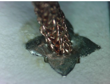
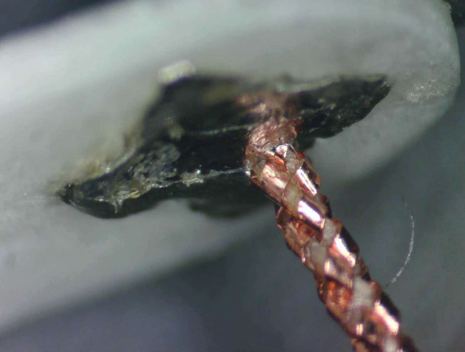
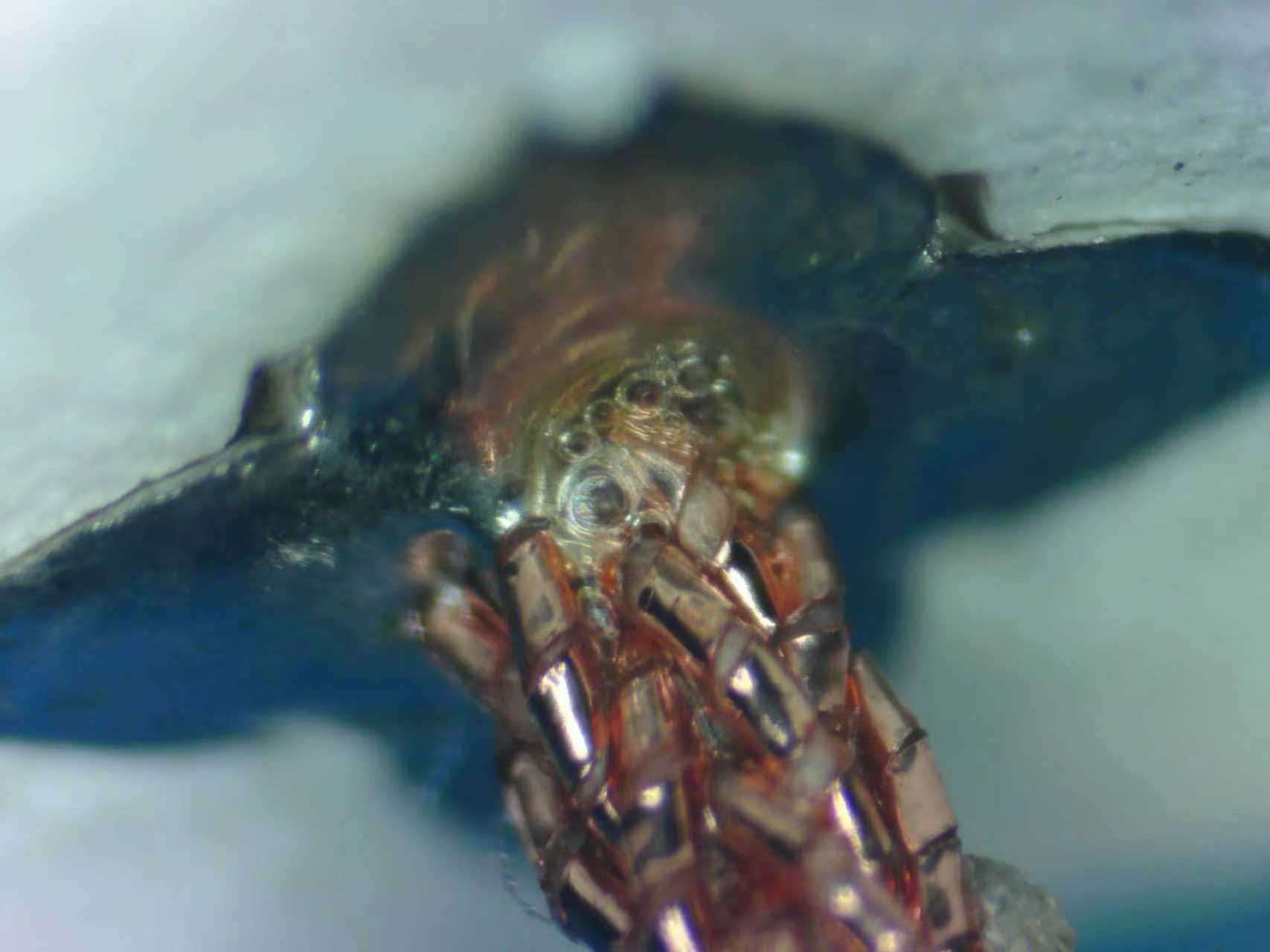
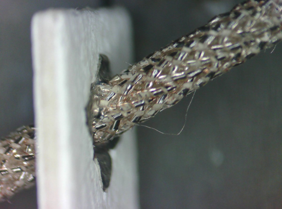
Actual Soldering Results · Optical Microscope 15×
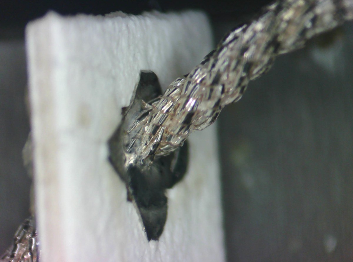
Braided-wire terminal soldering (back): 20-strand copper braid, no solder wicking or hardening.
Copper stranded-wire terminal soldering (back): 3-strand copper strand, no solder wicking or hardening.
Penetrant effect on the back: multiple copper foil strands are integrated into a single body.
Braided-wire terminal soldering (back): 20-strand silver braid, no solder wicking or hardening.
Silver stranded-wire terminal soldering (back): 16-strand silver strand, no solder wicking or hardening.
Soldering conditions: eco-friendly lead-free solder wire · constant-temperature iron at 370℃
CHRYPOO's innovative treatment gives tinsel wire moderate solderability together with support (shaped arcs hold their form), flexibility and internal damping (lower swing amplitude, clearly suppressing the "jump-rope" effect); at 370℃ lead-free soldering the terminal back shows no wicking and no hardening; the wire has high straightness and a smooth, fuzz-free surface — well suited to automated voice-coil wiring, with high stability and lower defect rates.
How to choose insulation and jacket? Tell us your operating temperature, oil/abrasion resistance and environmental requirements, and we will propose a material combination.
Describe the conductor requirements of your application and we will design and recommend suitable materials and structures. 400+ models to choose from.
Key Parameters Required for Customization
Provide the following information and CHRYPOO's engineering team will adjust the conductor structure, materials and processes accordingly, supporting long-term stable operation.
01
Wire Gauge / Outer Diameter (OD)
Specify the desired conductor OD — from ultra-fine wires to large cross-section strands, all can be evaluated.
02
Target Resistance (DCR)
Provide the target DC resistance level and we will configure the strand count and materials accordingly.
03
Application & Motion Conditions
Temperature, humidity, possible chemical contact — and most importantly the motion: bending, torsion or tension.
04
Expected Life
Desired reliability or cycle-life conditions, such as bending radius, cycle count and load.
05
Post-Processing Requirements
Processing needs: soldering / rolling / tinning, plus cut lengths and termination methods.
Reliability Test
What Determines Wire Reliability? The Conductor Is Key
Wire reliability is usually assessed by insulation class and EMI performance, but in dynamic applications the dominant failure mechanism is mechanical fatigue of the conductor. Repeated bending, torsion and continuous motion gradually harden conventional conductors, creating micro-cracks and eventual breakage. CHRYPOO builds test plans around real motion conditions and compares structures with data.
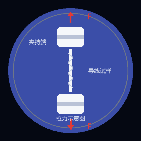
01 TENSILE
Tensile Test
Maximum breaking load (N) of the wire
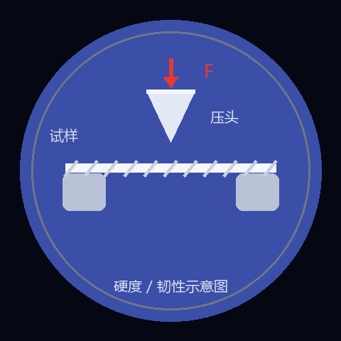
02 HARDNESS / TOUGHNESS
Hardness / Toughness Test
Measures the support of the wire within the speaker structure, evaluating resistance to failure from the jump-rope effect in operation.
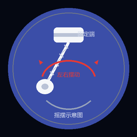
03 SWING
Swing Test
Applies repeated left-right swinging loads to simulate the daily swinging of earphone cables and wearables, recording cycles to failure.
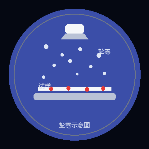
04 SALT SPRAY
Salt Spray Test
Simulates coastal or de-icing salt environments to assess the corrosion resistance of conductors, platings and terminations for long-term use without oxidative failure. Basic protection — 96H neutral salt spray test
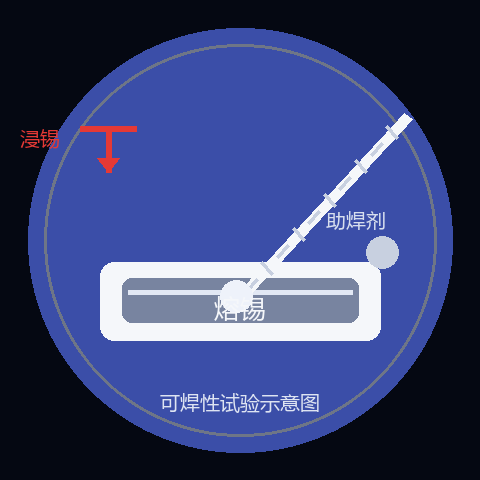
05 SOLDERABILITY
Solderability Test
Dips specimen ends into molten solder to measure wetting time and area, confirming plating and flux compatibility and avoiding cold joints and weak solder points.
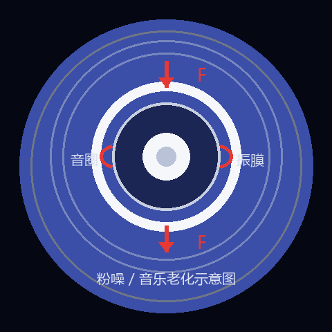
06 NOISE / MUSIC AGING
Speaker Pink-Noise / Music Aging
Drives speakers at high power for long periods with pink-noise, white-noise or music signals to simulate real listening conditions and test tinsel-wire failure.
Other Test Items
Constant high temperature / humidity: performance in hot and humid environments
Continuity & DCR monitoring: continuous monitoring of electrical drift during testing
Want to validate your own conditions? Provide bending radius, angle, frequency and load, and we will build a test plan around your actual motion conditions.
Engineering notes on conductor structure, life and selection.
How to Choose Wire with a Long Flex Life? Tinsel Wire vs. Conventional Stranded Wire
Conventional stranded wire is made of multiple round copper strands; under repeated bending each strand endures continuous tension and compression, gradually hardening and developing micro-cracks. A foil-wound structure lets the fiber core share part of the mechanical stress, reducing the risk of fatigue failure.
EMI and the Structure of Shielded Wire: Why the Outer Braid Matters More Than the Inner Conductor
Whether the core is solid, stranded or tinsel, a properly designed outer shield effectively blocks high-frequency noise and interference. Common failures include EMI leakage, signal attenuation and misreading by precision instruments.
Bending radius, angle, speed, frequency, load, temperature and failure criteria all affect results. If test conditions differ from real usage, a single cycle count cannot directly represent product life.